
Wiring
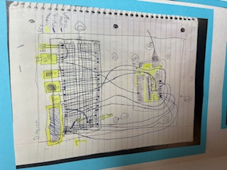
Here is the wiring diagram that I used on the board for the presentation.
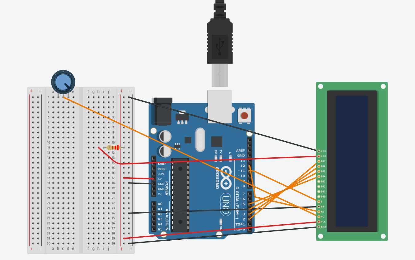
Then, here is a better wiring diagram made with Tinkercad. There was a slight problem though, because Tinkercad doesn't have some of the components that I used, like the DHT11 temperature and humidity sensor, so I could only show what the LCD wiring looked like. As for the remaining sensors, I used digital pin 7 for the DHT11 sensor and pins ~9 and 8 for the CO module and buzzer.
No comments to display
No comments to display