Designing
This is a description of my thought process along the way, and the project coming together.
Rubric
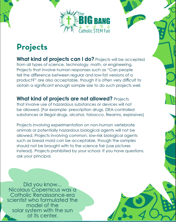
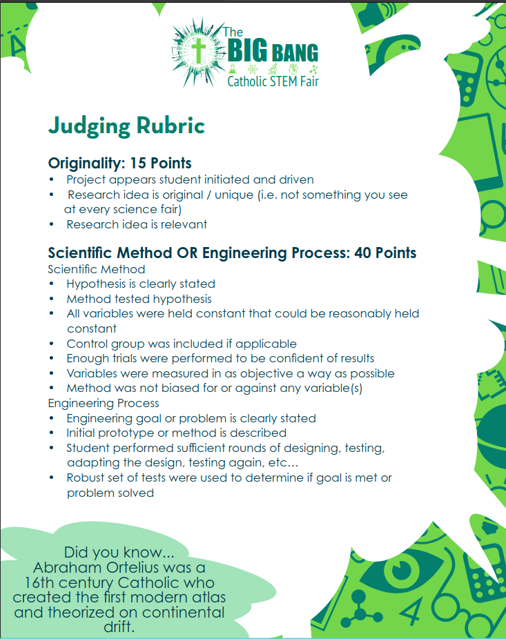
The CSCOE Big Bang science fair had this printed for all of the competitors, as a rubric and a guide. Unfortunately, there is no record of the original packet for 2023, I don't know why because there was a fair, but the only difference is the dates and the location.






Brainstorming
My original idea was to make a rover that would be sent to unknown areas and take temperature and humidity readings, plus has a carbon monoxide detector. My pi would be connected to a screen that displays the information received. The idea was to use the Elegoo v4.0 smart robot kit as sort of a base for the following additions.
Actually, I was at first thinking of making a bird encyclopedia website but that never worked out.
The original component list:
- 4 dc motors
- 4 wheels
- 2 plastic scraps
- a wood platform
- arduino uno
- raspberry pi 4 model b+
- 5 inch display screen (part of the freenove kit)
- servo motor
- arduino uno extension hat (called the robot car shield)
- ultrasonic sensor
- camera module
- plastic stand
- IR remote
- various hardware pieces
- battery
- battery pack
- USB C to outlet cord
- line tracker module
- black tape
- breadboard
- gpio extension board
- gpio wire connection
- jumper wires
- brass standoffs
- carbon monoxide detector module
Engineering Design Process
Engineering Design Process
- Define the problem
- Do background research
- Specify requirements
- Brainstorm, Evaluate, and choose solution
- Develop and prototype solution
- Solution either partly or fully meets requirements (testing)
- Communicate results

Defining the Problem/challenge
Building a rover that takes temperature and humidity readings, can avoid obstacles, detects carbon monoxide, and more. It can be used by firefighters, scientists, anybody who wants to be sure an area is safe.
Do Background Research
Robot can be used to fight fires or just explore a cavern, like a mini mars rover. Mars rovers do almost the same thing as my rover: temperature readings, rock and soil samples, and pictures. With more developments, it could become a rover, checking if somewhere is suitable for human life. In this way, it is a lot like a Mars rover.
Rover picture: Base rover project:

Specify Requirements
Carbon monoxide detector temperature and humidity sensor, mounted with the Arduino and breadboard, and jumper wires on top of the robots. The LCD will display the temperature and humidity readings. The Arduino will control and power the sensors. Another rechargeable battery powers the screen.
Brainstorm, Evaluate, and Choose Solution
Using the Elegoo robot as a base, adding cool sensors and a screen to the top to complete the requirements.
#include <DHTStable.h>
#define DHT11_PIN 7
DHTStable dht;
void setup() {
Serial.begin(9600);
}
void loop() {
int chk = dht.read11(DHT11_PIN);
Serial.print("Status: ");
Serial.println(chk);
Serial.print("Temp: ");
Serial.println(dht.getTemperature());
Serial.print("Humidity: ");
Serial.println(dht.getHumidity());
delay(1000);
}
This is the code for the dht sensor, also a test code.
Develop and Prototype Solution
Add a photoresistor module to detect light, program it to light an LED if there is light and red LED if no light. Another Battery, no Pi, only Arduino.
Materials and Procedures
There were many variations of each, I will start with oldest to newest.
The Original Materials List
- Elegoo smart robot car v4.0
- Photoresistor module
- Carbon monoxide module
- Temperature and Humidity sensor
- plastic platform
- Freenove 5 inch DSI screen
- GPIO extension board
- breadboard
- GPIO extension cable
- Raspberry pi 4 model b+
- jumper wires
The Original Procedure
- Assemble the robot following the instructions in the kit
- add the plastic platform using the support pillars and screws
- attach the rpi and screen to the platform
- wire the sensors
- code the sensors
- attach the battery to the platform with screws
- test the robot by driving it in light and dark, cold and hot, and place a lit match near the carbon monoxide detector
As you can see, these are a bit patchy.
Materials (Updated version)
- Elegoo smart robot car v4.0 with camera module
- Photoresistor module
- carbon monoxide module (Flying fish module)
- Temperature and Humidity sensor module
- chalkboard platform
- breadboard
- Arduino UNO
- computer
- jumper wires hardware
Procedure (Updated Version)
- assemble the robot
- ad the platform with screws and bolts
- wire the sensors
- code the sensors
- fix the UNO to the platform
- test the robot (driving in light and dark, cold and hot, place it by a lit match
Still quite patchy but it worked for a bit.
Materials (take 3)
- 16-2 LCD (Liquid Crystal Display) screen
- m7 Photoresistor module
- Flying Fish carbon monoxide module
- DHT11 Temperature and Humidity sensor
- a green LED
- an active buzzer
- a potentiometer
- 220khm resistor (5 band)
- Arduino UNO
- Raspberry Pi case
- double sided tape
- jumper wires
- mini chalkboard
- hardware
- Elegoo v4.0 smart robot car kit
- a drill
- a computer
- Arduino cord
- battery pack
- 8 AA batteries
Procedure (take 3)
- Assemble the Elegoo kit
- drill holes in the top platform and the chalkboard
- secure the chalkboard on top of the platform using 4 screws, 8 nuts, and 8 washers
- secure the breadboard onto the surface of the chalkboard with double sided tape
- put double sided tape on the bottom of the battery pack (with batteries in it) and fix it to the robot car
- secure the Arduino to the bottom of the Pi case using two small screws
- fix the Pi case and Arduino across from the breadboard with double sided tape
- wire the Photoresistor module and LED
- Photoresistor pin AO to analog zero (A0) on Arduino
- pin DO to LED anode (positive) pin
- pin GND to negative column on the breadboard (ground)
- pin VCC to positive column on the breadboard (voltage, 5v)
- LED cathode pin to negative column on breadboard
- Wire the DHT11 temperature/humidity sensor
- -pin to negative column
- out pin to pin 7 on Arduino
- + pin to positive column on breadboard
- Wire the CO module and active buzzer
- module pin DO to Arduino to digital pin 8
- GND pin to negative column
- VCC pin to positive column
- buzzer positive pin to digital pin ~9 on Arduino
- buzzer negative pin to negative column
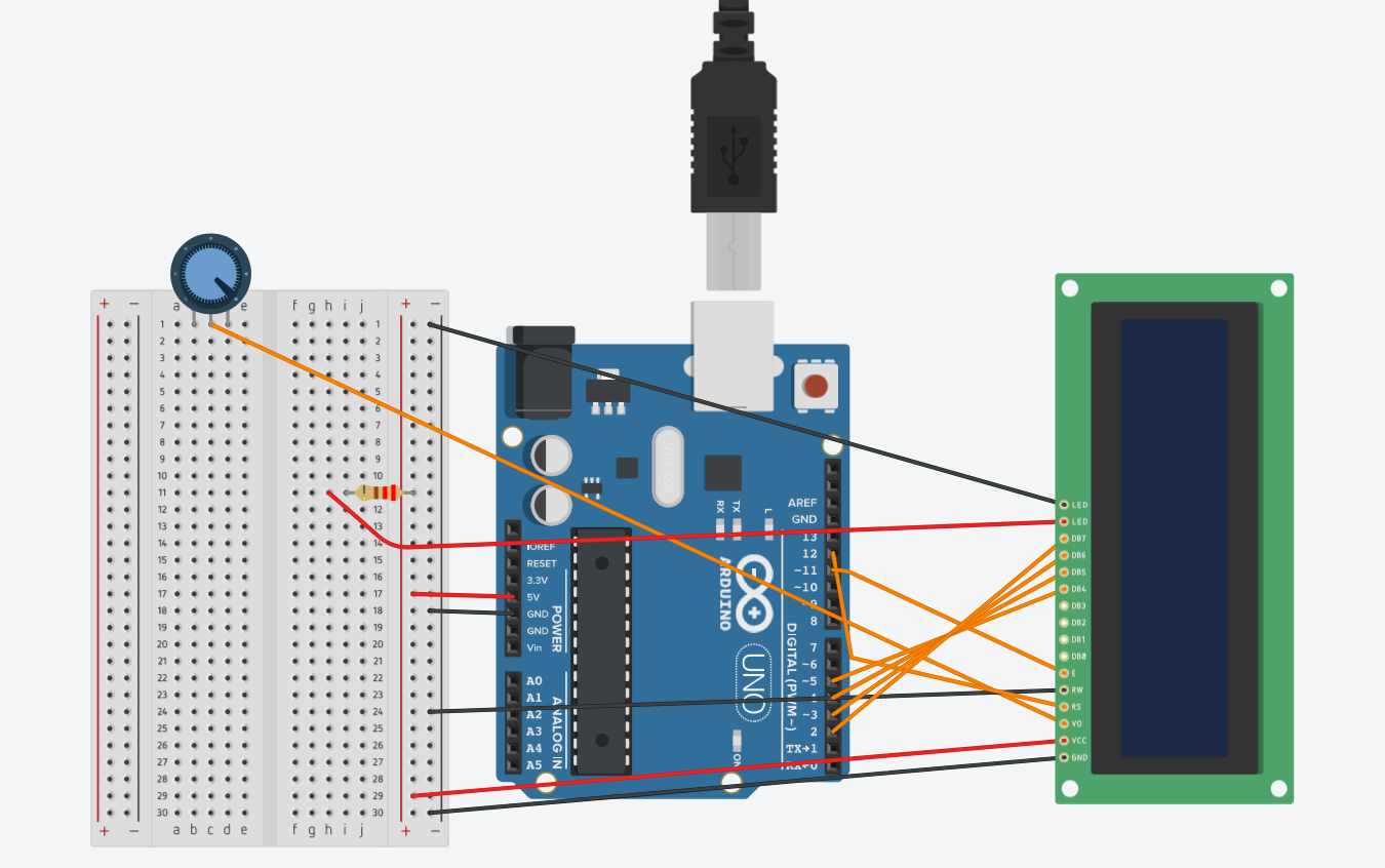
- Wire the LCD, resistor, and potentiometer
- LCD pin 1 to negative
- LCD pin 2 to positive
- LCD pin 3 to middle of potentiometer
- LCD pin 4 to digital pin 12
- LCD pin 5 to negative
- LCD pin 6 to digital pin ~11
- LCD pins 7-10, nothing
- LCD pin 11 to digital pin ~5
- LCD pin 12 to digital pin 4
- LCD pin 13 to digital pin ~3
- LCD pin 14 to digital pin 2
- LCD pin 15 to resistor to positive
- LCD pin 16 to negative
- Potentiometer left pin to positive
- Potentiometer right pin to negative
- Potentiometer middle pin to LCD pin 3
- Wire the Arduino to the breadboard
- Super simple, just 5v to positive and GND to negative
- Write the code
- Upload the code
- connect for testing
- test the robot
- record results
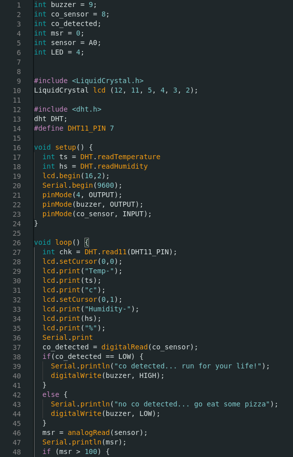
The Code
There were a lot of draft codes, like a lot, which is why these are the finalized code. Who wants to see broken code?
int buzzer = 9;
int co_sensor = 8;
int co_detected;
int msr = 0;
int sensor = A0;
int LED = 4;
#include <LiquidCrystal.h>
LiquidCrystal lcd (12, 11, 5, 4, 3, 2);
#include <dht.h>
dht DHT;
#define DHT11_PIN 7
void setup() {
int ts = DHT.readTemperature
int hs = DHT.readHumidity
lcd.begin(16,2);
Serial.begin(9600);
pinMode(4, OUTPUT);
pinMode(buzzer, OUTPUT);
pinMode(co_sensor, INPUT);
}
void loop() {
int chk = DHT.read11(DHT11_PIN);
lcd.setCursor(0,0);
lcd.print("Temp-");
lcd.print(ts);
lcd.print("c");
lcd.setCursor(0,1);
lcd.print("Humidity-");
lcd.print(hs);
lcd.print("%");
Serial.print
co_detected = digitalRead(co_sensor);
if(co_detected == LOW) {
Serial.println("co detected... run for your life!");
digitalWrite(buzzer, HIGH);
}
else {
Serial.println("no co detected... go eat some pizza");
digitalWrite(buzzer, LOW);
}
msr = analogRead(sensor);
Serial.println(msr);
if (msr > 100) {
Serial.println("soft light");
digitalWrite(4, LOW);
}
else {
Serial.println("hard light");
digitalWrite(4, HIGH);
}
delay(1000);
}
The Finalized code

Wiring
Here is the wiring diagram that I used on the board for the presentation.
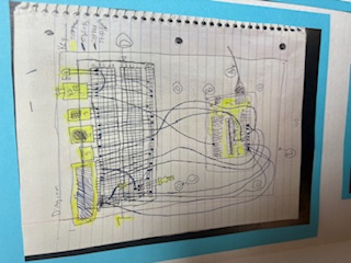
Then, here is a better wiring diagram made with Tinkercad. There was a slight problem though, because Tinkercad doesn't have some of the components that I used, like the DHT11 temperature and humidity sensor, so I could only show what the LCD wiring looked like. As for the remaining sensors, I used digital pin 7 for the DHT11 sensor and pins ~9 and 8 for the CO module and buzzer.